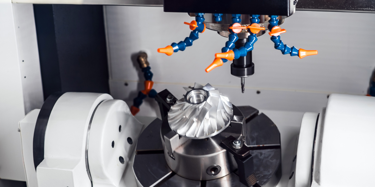
As Computer Numerical Control (CNC) machining has continued to prove its worth in the machining industry, the technology has continued to improve. Gone are the days when a machine could only perform one task in the production process with the part getting passed around from one machine to the next in a proverbial “musical chairs” of production. Instead, we have machines that can mill, turn, drill, and grind simply because they are told to. The result is more complex parts that are made more efficiently and with precision accuracy.
Check out our Guide to CNC Lathes
The key to this process comes from advancements in technology that allows for more sophisticated machines to craft parts in 5 and 6 axes (with a long E). This somewhat theoretical mathematical principle has been brought into the practical world in part through machining. The principles are complex and difficult to wrap your head around, even for us in the machining world, so let’s dig in.
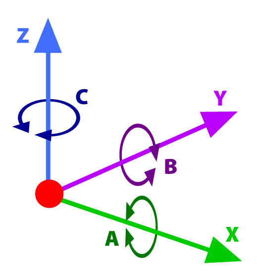
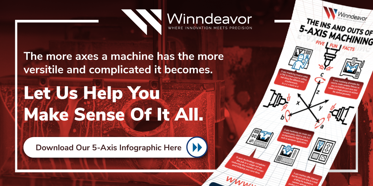
The X, Y, and Z axis representing three-dimensional space and their rotational axis represented by A, B, or C.
Three Axis
Think back to algebra. If you ever had to draw a linear graph, then you already know two of our five axes. And if you live on earth, you know the third one. That graph you drew back in school dealt with two axes: X and Y. Now, you probably thought of these two axes as Y being your up-down line and X as the left-right. This perfectly understandable, but consider this perspective: think of a piece of graph paper sitting on a table in front of you; the lines pointing at and away from you are the Y axis and the horizontal lines are still the X axis. Now, take a pencil and put the point in the middle of the paper with the eraser pointing straight up at the ceiling. Congratulations, you’ve just created the Z axis. The Z axis is what gives us height in three-dimensional space.
Imagine there’s a fly in your bathroom and the bathroom’s floor and walls are lined with identical square tiles. In theory, you could pinpoint where exactly the fly is in the room by identifying which floor tile it flies over—the X,Y axis—and which tile on the wall it flies across from—its Z axis. If you could imagine that, then you have replicated the process mathematician Rene Descartes thought up when he, according to legend, created the Cartesian system for graphing.
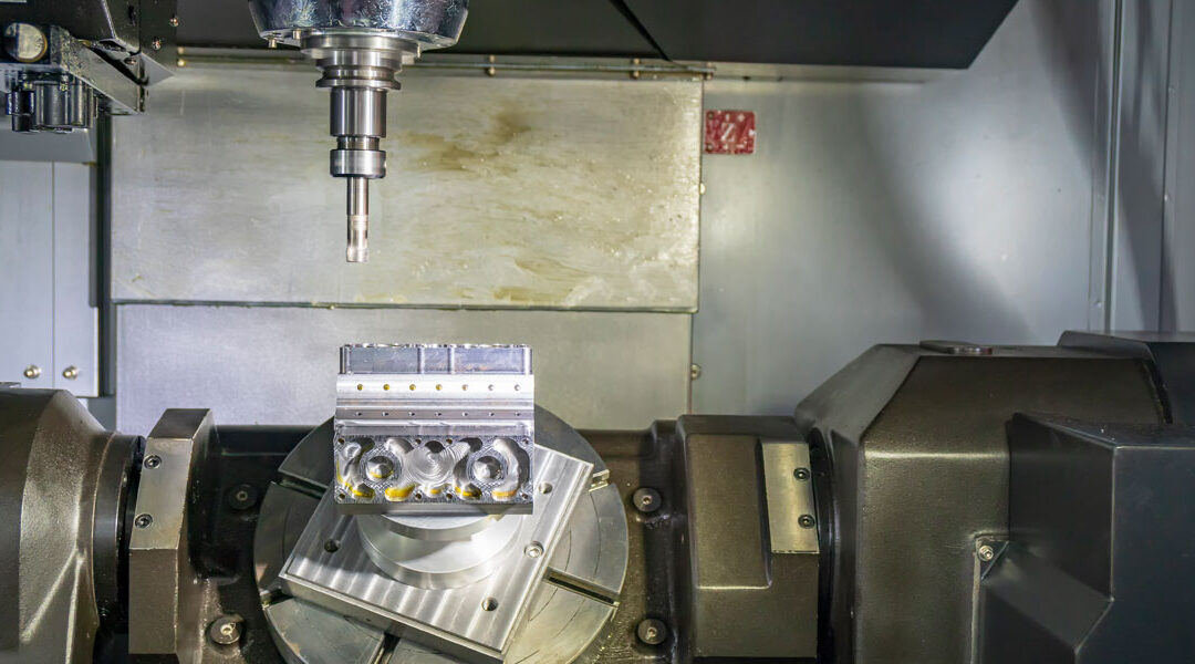
A 5-Axis Machine manipulating a part in order to make its complex cuts.
Two More Axes
So we’ve explained three axes—what about the last two? The first three are so practical, what could we possibly need two more for? Imagine your piece of graph paper with the pencil standing in the middle of it. Now poke a hole in the paper and pull it halfway up the pencil. Spin and tilt the paper (preferably the paper is stiff so gravity doesn’t make it droop). When you do, you are actually working in six axes!
When you spin the paper around the pencil (the Z axis), you are replicating the C axis. Tilting the paper so the edge facing you goes up or down replicates the A axis and tilting so the left and right sides go up and/or down replicates the B axis. Five- and six-axis machining does the same thing! Five axis machines can move and manipulate the workpiece so the tool can access different parts of the piece and shape it in five axes to create pieces like turbines without moving the piece from one machine to another. Six-axis machines allow for the head to move more dynamically around the workpiece. Six-axis machining does allow for greater range of motion, but it can sometimes be redundant for jobs that do not need require the sixth axis.

